These days, you can pretty much put the term ‘Software Defined’ in front of any technology or acronym – wide area network (WAN) is the next up-and-coming example: SD-WAN. The Citrix solution is known as Citrix Virtual WAN and it is a part of the CloudBridge product line – more information is available here. What is Virtual WAN exactly? It is an appliance that allows multiple WAN connections at your remote offices to be virtualized into a single, logical connection – thus affording a dynamic, optimized, and fault-tolerant connection back to the datacenter.
And I don’t mean multi-second (or even minute\hour when manual intervention is required) failover; Citrix Virtual WAN monitors individual packets rather than sessions to make routing decisions on the fly, in about the time of a single round-trip – milliseconds. What does this mean for your business?
- Allows you to aggregate bandwidth using cheaper connections – 4G, cable, DSL
- Failover is instantaneous and seamless to end users
- Prioritization and QoS applied to all traffic based on type
- A more resilient, higher throughput network
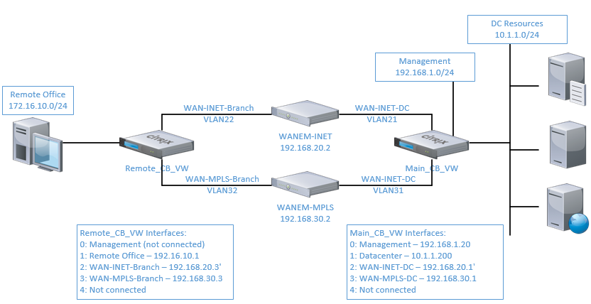
In this post I’m going to cover a basic example of configuring Citrix VirtualWAN in your lab environment. Note that this example is all virtual – meaning that there are no ‘real’ network or internet connections and the VWAN appliances are also virtual. Additionally, we will be using virtual WAN emulator appliances to simulate packet loss, latency and jitter on the ‘WAN’. This configuration may seem overly complex – and it is – but this is due to the fact that it is designed to be deployed as an “all virtualized demo”.
Use the following diagram for reference:
Notes about this configuration
- Due to some limitations of the virtual ‘VPX’ VWAN appliance, this demo must use the ‘gateway’ deployment model, meaning that hosts use the VWAN appliance as their gateway – the preferred method is ‘transparent’ or inline mode
- Use caution when implementing this configuration – ethernet bridging can cause network loops
- Hypervisor configuration may be required to allow for MAC address spoofing and\or forged transmits on the virtual switches
Requirements
- 7 different VLANs on your switch gear and hypervisor
- 2 for each used subnet (datacenter and branch office)
- 4 for each simulated network segment
- 1 for management of the VWAN MCN
- 5 different subnets on your switch gear and hypervisor
- 2 for each simulated WAN
- 2 for each used subnet (datacenter and branch office)
- 1 for management of the VWAN MCN
- 2 Cloudbridge VirtualWAN 8.1 appliances
- 2 Cloudbridge VirtualWAN evaluation licenses
- 2 WANem 3.0 VMs – available here
- Read the CloudBridge documentation at least twice
Configuration Steps
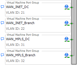
- Create additional subnets and VLANs on your network and hypervisor (as needed)
- VLAN 21 – WAN-INET-DC (192.168.20.0/24)
- VLAN 22 – WAN-INET-Branch
- VLAN 31 – WAN-MPLS-DC (192.168.30.0/24)
- VLAN 32 – WAN-MPLS-Branch
- Deploy WANem VMs and create the virtual WAN segments
- Note – I am booting the WANem VMs from CDROM, so the config is not saved
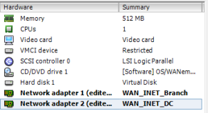
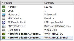
- Configure each WANem in bridge mode
- Run the following commands from the console (note the IP addresses will be different for each WAN segment):
- exit2shell
- ifconfig eth0 0.0.0.0 up
- ifconfig eth1 0.0.0.0 up
- brctl addbr br0
- brctl addif br0 eth0
- brctl addif br0 eth1
- ifconfig br0 192.168.20.2 netmask 255.255.255.0
- route add default gw 192.168.20.1
- wanem
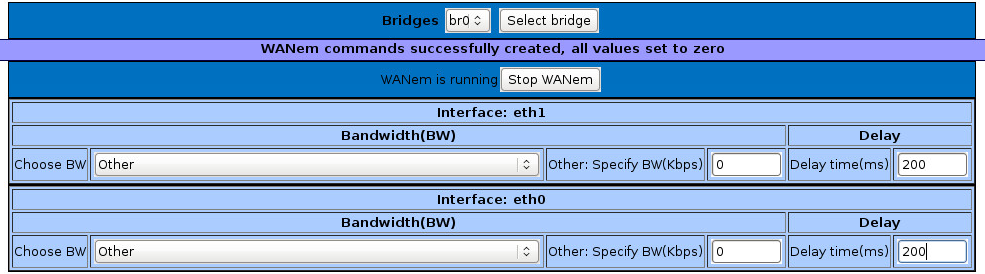
- With WANEM 3.0, WAN configuration changes can be made from the console of the VM
- Run the following commands from the console (note the IP addresses will be different for each WAN segment):
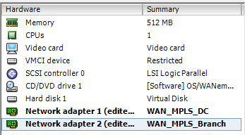
- Deploy the two CloudBridge VirtualWAN appliances
- Take note that binding order of the interfaces is important as it is reflected in the site configuration
- Interface 0 is always management, and it must be bound to a network, even if it is not connected so that interface 0 is populated
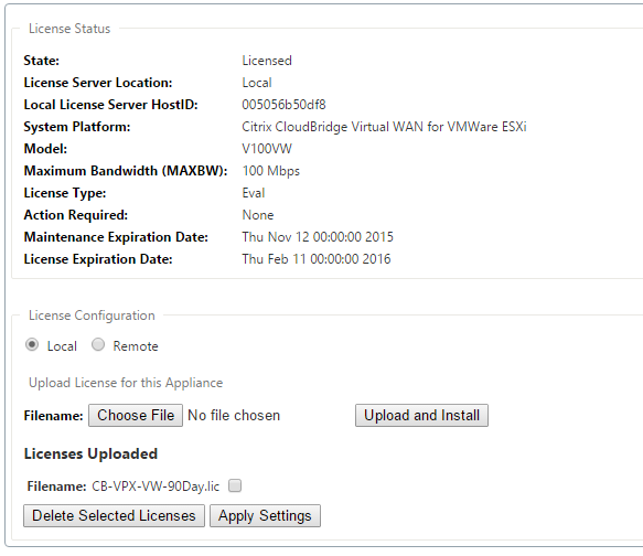
- Configure the management interface of the MCN and branch office appliance
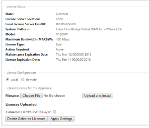
- Login to the web console of the appliance (admin\password) and under configuration, set the time
- Apply the evaluation license file – note it is based on MAC address for the VPX
- Promote the DC appliance to MCN user interface (see the documentation above)
- Take note that binding order of the interfaces is important as it is reflected in the site configuration
- Build a configuration on the MCN
- Familiarize yourself with the both the configuration building process and change management proces outlined in the documentation, I am not going to cover it in detail here.
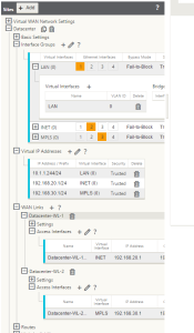
- Define two sites: Datacenter and Branch
- For each site, configure the following:
- Interface groups
- Virtual IP addresses
- WAN Links
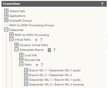
- Verify the auto-created connections – you will likely need to create the 2nd path
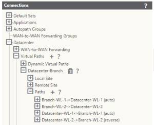
- Once completed, the configuration should look something like this:
- Apply the configuration to the MCN using Change Management (ignore incomplete)
- Stage and apply the branch configuration to the branch appliance
- Download the config ZIP file for the branch appliance from the MCN
- Logon to the branch appliance
- Go to local change management and upload the config file
- Ensure that the Virtual WAN service is started on both appliances


Testing
Now that you’ve got the virtual branch office configured, the monitoring tab on the appliance will show you the quality of the paths to the branch.
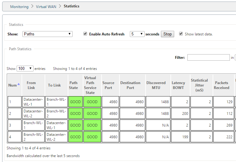
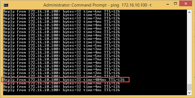
Note that each line a one way link between the sites. To show just how quickly Virtual WAN will migrate packets to a better path, we’ll introduce 400ms of latency (200ms on each link).
A running ping trace will show the 400ms spike for one response, but the next response will be back to normal (in this case, normal latency is ~4ms due to the network configuration and wanem appliances).
Further testing using iperf can be done to demonstrate that all available bandwidth will be used. At this point, feel free to modify the WAN characteristics using the WANEM appliances to modify bandwidth, latency, jitter, etc – and watch the Citrix Virtual WAN take care of the rest.