I’ve been talking and working a LOT with NetScaler SD-WAN lately – and I noticed that my first post (here) still has the name of Cloudbridge VWAN. If you don’t know what it is, the best way to explain it is with a short video.
It’s cutting edge technology for your WAN!! So to make things right, and add to the previous post – I’ll be covering how to build a simple, initial SD-WAN configuration for a PoC or demo environment. Much of the network layout is the same as in the previous post, so I recommend reviewing it; alternatively, feel free to adapt the configuration to suit your needs – there are a lot of options here: network layout, routing configuration, mode of deployment, etc. In this example, I am keeping with ‘Gateway Deployment Mode’ at the branch office site to keep it simple, but feel free to throw in another router and configure the SDWAN appliance in ‘Inline Mode’.
The Environment
This will be using a very similar environment to the previous post – that said, I’m going to use the same diagram for basic reference:
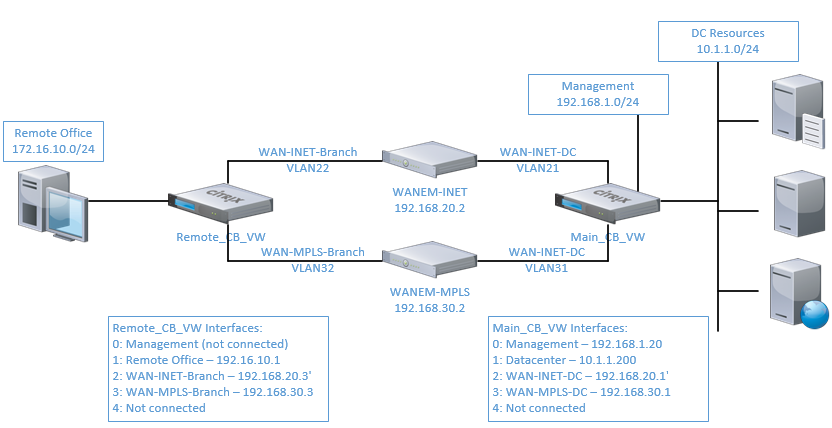
All systems will be virtual machines – the NetScaler SD-WAN boxes will be VPX appliances and WANEm virtual machines will be used for simulating conditions of a wide area network. There will be 2 simulated WAN networks: in this example they will both be bulk internet for simplicity, though you can configure MPLS if you would like. Here’s what you need to get started:
- 8 different VLANs and IP spaces on your switching and hypervisor infrastructures (3 of these are optional – noted below as re-used)
- 1 for each client subnet = 2 (datacenter and branch office – note that I re-used my lab subnet as the datacenter here)
- 1 for each simulated WAN network segment = 4
- 1 for management of the SDWAN appliances = 2 (I re-used the both the lab subnet and branch office subnet for management)
- 2 NetScaler SD-WAN Standard Edition VPX appliances
- 2 NetScaler SD-WAN evaluation licenses
- 2 WANEm VMs (note that I used v2.3 in this example)
IP Space and VLANs in this demo:
- 10.1.2.0/24 VLAN2 = Datacenter (Lab subnet as well; MCN management)
- 192.168.20.0/24 VLAN21 = Datacenter side of bulk internet; VLAN22 = Remote side of bulk internet
- 192.168.30.0/24 VLAN31 = Datacenter side of MPLS internet; VLAN32 = Remote side of MPLS internet
- 172.16.10.0/24 VLAN172 = Remote site (Remote SDWAN management)
Getting Started
First, let’s get the WAN environment configured – use the WANEm 2.3 ISO from here to build 2 VMs. It will boot into LiveCD mode, but to make things easier we are going to install it to the HDD. That said, make sure that you have an HDD allocated to the VMs; for the networks, I’ll be using the bulk internet VLANs for one VM and the MPLS internet VLANs for the other. Remember to use the two different pairs of network segments as well as two different IP addresses for the bridge interface on the WANEm VMs – this will be the IP used to manage the WAN emulator.
To get WANEm deployed to HDD rather than always booting to LiveCD, use the following post: https://www.citrix.com/blogs/2015/07/06/ingmarverheij-setting-up-a-persistent-wan-emulator/
Next, we need to get the bridge configured on each of these VMs such that they will be auto configured at boot. Add the following lines to /etc/network/interfaces (note: use your IP address netmask and gateway):
auto br0
iface br0 inet static
     address 192.168.20.2
     netmask 255.255.255.0
     gateway 192.168.20.1
     bridge_ports all
     bridge_fd 0
     bridge_stp off
Once completed, reboot the WANEm VM and double-check that the bridge interface br0 comes up – browse to http://192.168.20.2/WANEm from a system on the network.
Next, we need to deploy the NetScaler SD-WAN appliances – these will be deployed in the Datacenter subnet and remote office subnet with additional links for management and WAN connectivity. The latest GA build at the time of this writing is 9.1.2 and can be downloaded from www.citrix.com. A few notes on getting these VMs deployed:
- Network interface binding order is important as it is reflected in the site configuration
- Interface 0 is always management and must be bound to a network even if it is not connected or utilized such that interface slot 0 is populated
- I am using the datacenter and remote office subnets as management as well
- Once deployed, hop into the console to do the initial network configuration
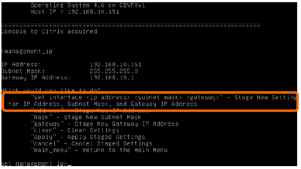
To set the management IP address, do the following:
- You may have to press ‘Enter’ for the console to appear
- Login using the default credentials of ‘admin’ and ‘password’
- Issue the following commands to set the IP (substituting your IP address details):
- management_ip
- set interface <ip address> <netmask> <gateway> (set interface 10.1.2.70 255.255.255.0 10.1.2.1)
- Once the above is entered, the new IP address will be staged
- To apply the staged configuration, enter: apply
- Enter y to confirm
- You should now be able to login to the web console: http://10.1.2.70 using the same credentials
Complete this process on both the SD-WAN appliance in the datacenter as well as the remote office.
Take this time to also make sure that any additional routes are in place – for example, you will likely need a route for the branch office by way of the SD-WAN interface in the datacenter:
172.16.10.0/24 via 10.1.2.71
There are additional route settings needed, but these will be covered in the configuration section.
Basic NetScaler SD-WAN Configuration
To get started, we need to set a few basic things prior to building our first SD-WAN configuration file. When logging in to the web console for the first time, you may be prompted for a quick start deployment – this can be used on the branch office appliance once you have built a valid configuration. Alternatively, complete the below process on both the datacenter and remote SD-WAN appliances. Log in to the appliance in the datacenter and do the following:
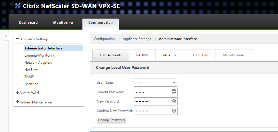
- Go to the Configuration tab under Appliance Settings > Administrator Interface
- User Accounts tab: change the default admin password
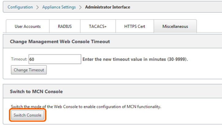
- Miscellaneous tab: change the console timeout to a larger value, 600 minutes for example
- Miscellaneous tab: Switch Console to the MCN console to allow configuration changes
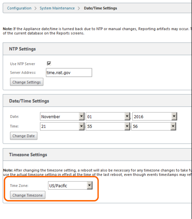
- Go to the Configuration tab under System Maintenance > Date/Time Settings
- Set an appropriate NTP server, ensure the current timezone is set, and ensure the time is set correctly
After making the changes above, you will be redirected to log back in to the web console. After logging back in, proceed to install the license file – it is based on the system MAC address.
- Go to the Configuration tab under Appliance Settings > Licensing
- Upload the license file that matches the MAC address of the system.
Building the Initial SD-WAN Configuration File
You may have noticed that the Citrix Virtual WAN service has been disabled – this is due to the lack of configuration (an invalid, or missing license file can also cause the service to be disabled) – we will build the configuration now.
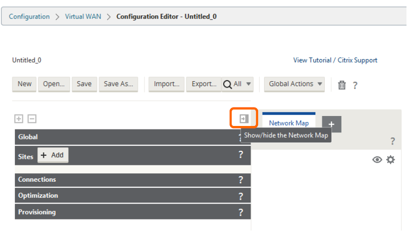
The remainder of the configuration will be done on the MCN SD-WAN appliance in the Configuration Editor located in the Configuration tab under Virtual WAN > Configuration Editor. Once you have started building the configuration, make sure to use the ‘Save As’ button to save the configuration file with a meaningful name – also make sure to frequently save the configuration using the ‘Save’ button. To give yourself more room to build the configuration, you can hide the Network Map area by using the ‘Show/hide the network map’ button depicted by a right arrow icon. Once you have built out a larger deployment, the Network Map area is a useful tool to quickly access areas of the configuration based on the location in the graphical map.
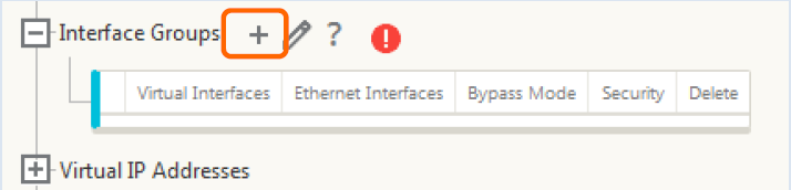
Familiarize yourself with the navigation of the configuration editor – there are a set of icons you will be working with:
![]()
- Each object is in a section, and sections can be expanded by using the +/- icons inside a square
- The (+) icon will add rows to the current configuration object
- The pencil icon will allow an object to be edited; *note: if you are in edit mode on an object, you will need to press the ‘apply’ or ‘revert’ buttons to exit from edit mode.
- The ? icon displays help for an object
- The trashcan icon deletes a row or object
- You can edit the name of some objects by clicking on the name text – this cannot be done if you are in edit mode on that object
Also, understand that while you are building the configuration, it is always being audited for errors – during the first go through, there will likely be errors until you finish the configuration and that is expected. For example, you will get an error when you initially configure the first site because there are no endpoints for those connections – this will be resolved when you create the remote site and add the WAN links for that site. The audit will NOT, however, pick up on incorrect IP addressing or netmasks, for example. Audit errors can be seen as red ‘!’ icons on the section with a configuration issue – hovering over them will give you a description of the error.
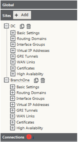
First, create a new configuration by selecting the ‘New’ button in the Configuration Editor. We then need to define each site in our network – we will start with the datacenter site.
Sites
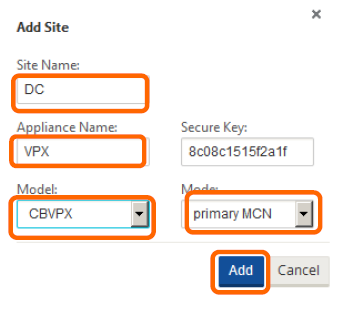
Under Sites, press the ‘Add’ button. For the site you need to define a site name, appliance name, the model of the appliance, and the mode of the appliance. The appliance model is used to provide context for the menu options in the configuration – how many ports are available for example.
You can create the additional remote site now, but it is recommended to build one site at a time – once the site configuration is complete and without audit errors, then create another site.
Interface Groups and Virtual Interfaces
Within the site we created, we need to configure the interface groups on the appliance – this is essentially where you configure the interfaces as bridge pairs or otherwise and define the bypass and security settings for them. To get started, click the (+) icon in the Interface Groups section.
Once you have configured the Ethernet interfaces (for VPX, you can only choose to highlight 1-4), bypass mode and security, select the (+) icon to create a new virtual interface to be tied to the physical interface groups. *note: do not click ‘apply’ until you have defined the virtual interfaces for each of the interface groups.
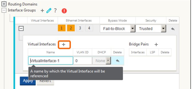
The above example is specific to having interfaces 1 and 2 set for bridge mode – to complete this configuration, click the (+) icon for ‘Bridge Pairs’ and assign the two interfaces 1 and 2 in this example. Also note for VPX appliances, fail-to-wire is not supported, only fail-to-block. If you are not configuring bridge pairs, this is not required. Repeat these steps to configure all the interfaces on the appliance (note the screenshot below – interfaces 3 and 4 are not in bridge mode and do not have bridge pairs configured).
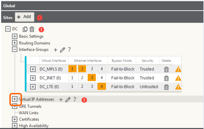
Virtual IP Addresses
Virtual IP addresses define the IP space for the data plane and these are the IP addresses that will be used to put the packets on each of these links – also note that one of these virtual IP addresses on the branch network will be used as the client gateway. Create the IP addresses and bind them to their associated virtual interfaces created previously. *note: enter the IP addresses in IP address/mask prefix format.
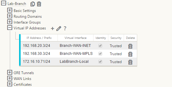
*Remember to save*
WAN Links
Under the WAN Link header, create a new WAN link – specify a name for the WAN link and specify the access type. For access types, select private MPLS to enable QoS\DSCP settings on the WAN link; select Public Internet to be able to use autodetection of Public IP if the link needs to pull the IP address from the ISP via DHCP and when security is required; use private internet for all other connections. For the purposes of this demo\PoC, I will be using all private internet. For each link, you need to define the physical rate of the interfaces – the permitted rate is set from the physical rate by default, but if there is other traffic on this WAN link, you can override the permitted rate to allow headroom for the other traffic on the link.

If you want to simulate 3G\4G\LTE traffic, set the configuration for the WAN link to include metering on the link and\or last resort. To complete the WAN link configuration, you need to bind it to an access interface – this cooresponds to a virtual IP and interface created previously. Additionally, you will need to define a gateway for this link – for this demo, we are using the virtual IP of the partner appliance as the gateway here. For actual production deployments, this would be appropriate for WAN services such as eLine where the IP is a private and the device is put on the same broadcast domain.
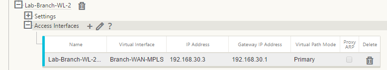
Also, remember to enable Proxy ARP for MPLS deployments that are in inline-mode.
Repeat the above process for each WAN link – in this example, there are 2 total WAN links.
**At this point, return to the sites section and create the 2nd site in the configuration.
Connections
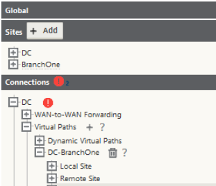
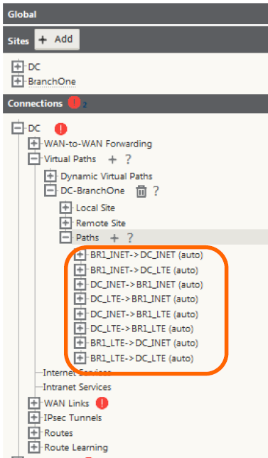
Once the 2nd site is created and has a valid configuration, there should not be any audit errors in the site section – but there will likely be errors in the connections section.
Open the connections bar and expand the datacenter site > Virtual Paths > DataCenter-RemoteBranch > Paths. You will notice that several paths have already been created – these auto-created paths come from public internet links as any internet WAN link tan terminate with any other internet WAN link at any other site.
*Remember to save*
In this example, only two of the paths were auto-created, but any number of paths will auto create.
For private links (including MPLS) we need to enable the links to be used – go to Connections > Datacenter > WAN Links > PrivateLink > Virtual Paths – choose the edit pencil, and check the box for ‘Use’
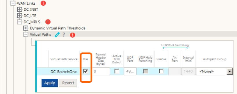
Do the same thing for the other side of the connection under Connections > RemoteBranch > WAN Links > PrivateLink > Virtual Paths
Lastly, you need to create the private path. Go to Connections > EitherSite > Virtual Paths > Datacenter-RemoteBranch > Paths – choose the (+) icon to add a path. In this example the only path to configure is between the datacenter and the remote branch – use the private link.
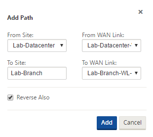
Ensure that the checkbox for ‘Reverse Also’ is checked – this will create the reverse path automatically.
There should no longer be audit errors in the configuration – if there are, go back through and observe what they are indicating to resolve them. Save the configuration again.
Change Control
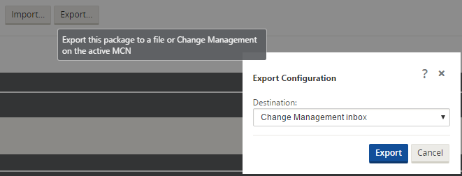
All configuration changes and firmware updates are made through the change management interface. When your initial configuration is ready, select the Export button in the configuration editor and select ‘Export to change management inbox’. We will now walk through the process to activate the configuration on the MCN.
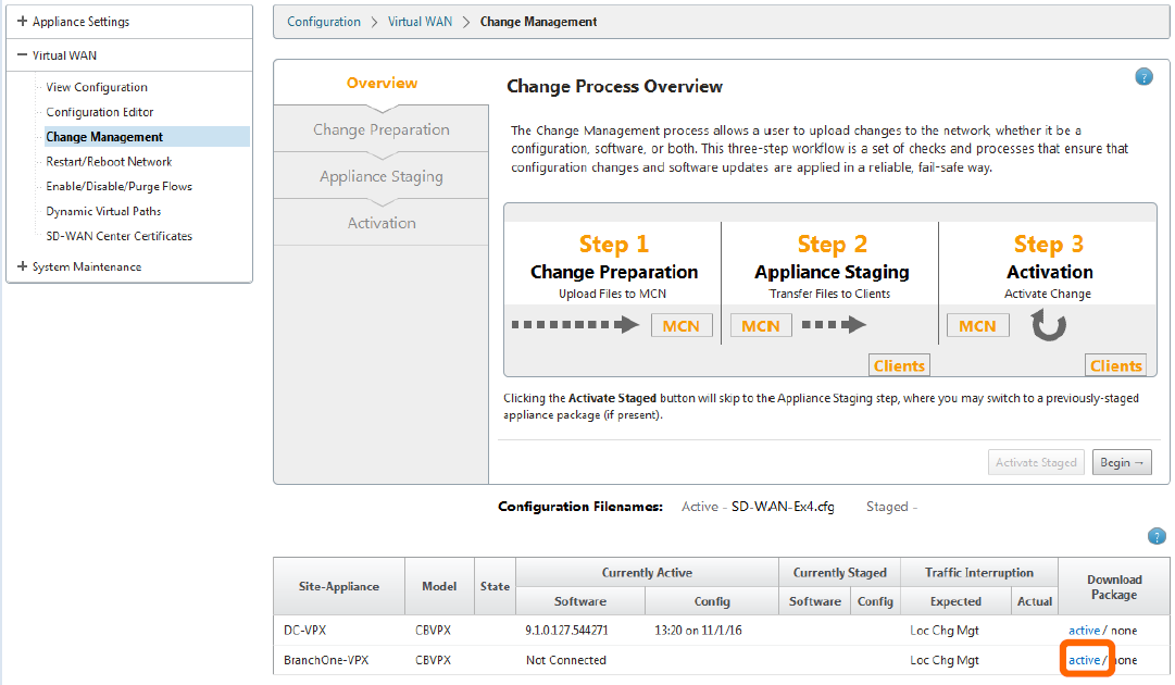
Proceed to the Configuration tab > Virtual WAN > Change Management. On the CM overview page, click the ‘Begin’ button to get started.
Change Preparation
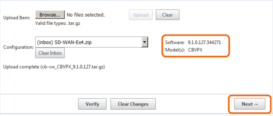
For the first change management process, you will need the configuration file as well as the current firmware for the appliances – firmware will be in tar.gz format and downloadable from www.Citrix.com. Note the current format for the upload file – this is specific to SD-WAN Standard Edition as well as the VPX appliance:
cb-vw_CBVPX_9.1.2.26.tar.gz
Choose Begin to start the CM process. The configuration file is already in the inbox, but you must manually upload the firmware file – browse to the location on your system, select the file then press upload to send it to the CM interface. Once successfully uploaded, the software will list the version number – click next.
You will be prompted to accept a license then be presented with a window to begin the change staging process. Additionally, if you need to upload a previous saved\exported configuration you can do that by using the browse button on this page.
Staging
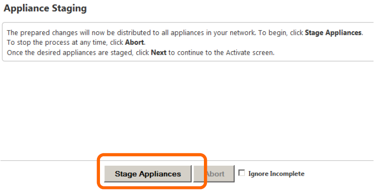
The staging step allows the configuration file as well as the firmware to be ‘Staged’ on all appliances in the environment – for our simple demo environment, staging on the DC and remote appliances will not take long at all, however – in a production environment, this may take some time to copy everything to all of the appliances. To begin the staging process, simply click ‘Stage Appliances’.
You will note a progress bar showing how far along the copy operation has progressed.
Activation
Once the copy is completed, you are presented with an activation screen – this allows you to activate all of the configuration and firmware changes to the environment. To do this, click the button labeled: ‘Activate Staged’

There will be an additional pop-up window prompting for your confirmation prior to activation.
Once the activation begins, the appliance will begin a countdown – the duration of this countdown depends on what is being activated. For the initial activation which includes firmware, the counter will start at 180 seconds. For smaller changes where only configuration is being modified, the counter will start at 30 seconds. *note: it may not take the full amount of time in the countdown
Once activation is complete, you should be returned to the CM window with a Done button.

Enabling the Citrix Virtual WAN Service
Now that the configuration has been applied on the MCN, the Virtual WAN service can be successfully enabled. To do that, go to Configuration > Virtual WAN > Enable\Disable\Purge Flows and click on the ‘Enable’ button.
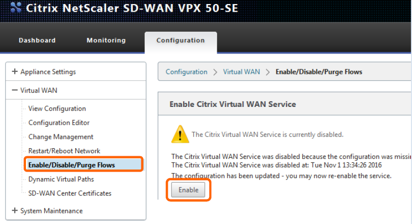
Note that the monitoring pane will still show all paths as dead since the remote office appliance still does not have any configuration.
Configuring the Remote SD-WAN Appliance
If you have not already done so, set the appliance management IP address from the hypervisor console as defined in the ‘Getting Started’ section of this post. Next, we need to download the remote office configuration file from change management on the MCN appliance – this will be a .ZIP file.
*Note: Ensure that you download the remote office package rather than the MCN\DC package.*
Open a web browser to the remote NetScaler SD-WAN appliance. If you have not already done so, configure the time settings and licensing as defined in the ‘Getting Started’ section of this post.
Proceed to the local change management section under: Configuration > System Maintenance > Local Change Management – Click ‘Begin’ and proceed to browse for the previously downloaded remote site .ZIP file – *note: ensure that it is the remote office configuration file. Ensure that the ‘Upload’ button is pressed once the file is selected – click ‘Next’ to continue.
After validation, you will be presented with an ‘Activate Staged’ button just as one the MCN appliance. Proceed with the activation as before – once activation is successful, click the ‘Done’ button.
You may now enable the Virtual WAN service on the remote appliance under Configuration > Virtual WAN > Enable\Disable\Purge Flows
Completion
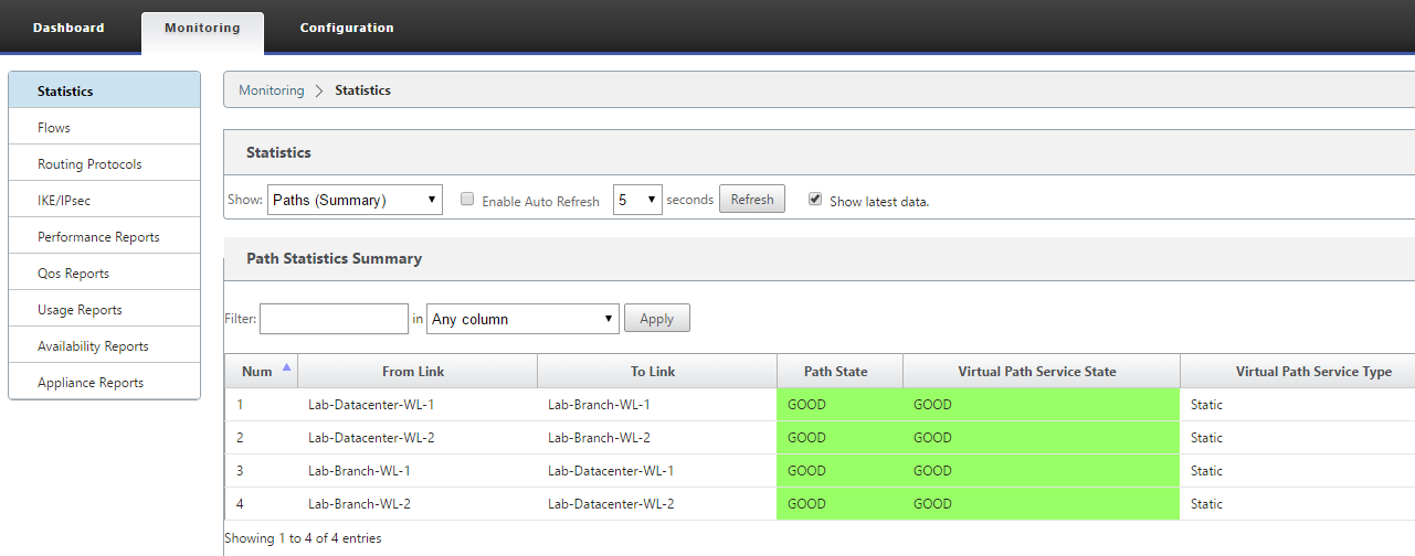
Once the Virtual WAN service has been enabled on both appliances, the monitoring tab should begin to show paths in the ‘Up’ state.
Notes:
- Be sure to set routes for any other subnets not in the configuration – especially when deploying in gateway mode for the branch office. This is done within the configuration under Connections > Site_Name > Routes
- Once you have an initial configuration on all appliances, configuration updates using Change Management will take significantly less time to activate. Additionally, the CM process will give an estimation of how much (if any) network interruption will occur during the change, and once completed, will display how much interruption actually occurred. Note the ‘Expected’ and ‘Actual’ columns.

- Depending on network topology, there may be a need to address asymmetrical routing for this demo – for example, the traffic destined for the ‘datacenter’ subnet is on the same subnet as the local VIP, however on the return trip, traffic will be sent to a gateway before being sent over the SD-WAN network. This scenario is only specific to this demo environment and would not happen in a production deployment.
Troubleshooting:
- Check the WANEm VMs to ensure that the bridge interface has been configured and is up and running
- If the Citrix Virtual WAN service is not enabled, check that a valid license has been installed and ensure that there is a valid configuration loaded
- Hypervisor virtual switches may require promiscuous mode\forged transmits\MAC address changes to be enabled
- Ensure that NICs are bound in the correct order (Management is always port 0) and enabled